1. The Haunting Nightmare of Electroplating Blisters: A Production Forensic
Every die-casting factory director has lived through the nightmare of 'delayed electroplating blisters.' The parts emerge from the hydraulic die-casting machine looking pristine. They pass through vibratory deburring with mirror-like smoothness. They receive bright copper, nickel, and real gold plating, shining brilliantly on the final inspection table before being packaged and shipped overseas.
Then, forty-five days later, as the container ship crosses the tropical waters of the Pacific Ocean where cargo holds reach 50°C and 90% relative humidity, disaster awakens inside the metal lattice. Microscopic pockets of trapped air and vaporized lubricants beneath the paper-thin electroplating skin expand under heat. Tiny pimples, blisters, and craters erupt across the keychain's polished face, causing the gold and nickel layers to peel away in hideous blisters.
In 2016, our factory had to scrap an entire run of 80,000 custom automotive key fobs due to this exact defect. The financial loss exceeded $45,000 USD, but the hit to our engineering pride was far more painful. That failure led me to launch a complete, multi-year overhaul of our metallurgical protocols, mold runner fluid dynamics, and vacuum extraction systems. Today, I want to take you deep inside the physics of Zamak-3 zinc alloy die-casting to show you exactly how these defects occur and how we eliminate them forever.
2. Zamak-3 Metallurgy: The Balancing Act of Aluminum, Magnesium, and Purity
Zinc die-casting alloys are extraordinary materials. They melt at relatively low temperatures (around 385°C to 395°C), flow like water under pressure, and can replicate microscopic tool markings with fidelity down to 0.02mm. For 90% of custom keychain manufacturing, we utilize Zamak-3 (ASTM AG40A / EN 12844 ZL0400).
The chemical composition of Zamak-3 is an exquisitely tuned metallurgic balance: 3.9% to 4.3% Aluminum, 0.02% to 0.05% Magnesium, and maximum 0.25% Copper, with the remaining 95.5% ultra-pure high-grade zinc (99.995% Zn).
Each element plays a non-negotiable structural role:
Aluminum reduces the melting point, increases fluid fluidity during cavity filling, and forms an iron-aluminum intermetallic barrier film that prevents molten zinc from chemically soldering onto our H13 tool steel die walls. However, if aluminum drifts above 4.5%, the alloy becomes excessively brittle and prone to impact fracture.
Magnesium is added as an antidote to intergranular corrosion. In the presence of trace impurities, zinc grains can undergo severe chemical degradation along their boundaries in humid environments. Magnesium prevents this by altering grain boundary surface energy. But if magnesium exceeds 0.06%, it drastically reduces liquid fluidity, leading to severe cold shut defects in thin keychain tabs.
The deadly impurities: Lead (Pb), Tin (Sn), and Cadmium (Cd) are the mortal enemies of zinc casting. If lead exceeds 0.005% (50 ppm) or tin exceeds 0.002% (20 ppm), the alloy will develop delayed intercrystalline swelling, warping and disintegrating into powdery gray dust after two years of atmospheric exposure. This is why our foundry rejects cheap scrap zinc ingots and only melts virgin, certified primary Zamak-3 ingots accompanied by spectrometer heat certificates.
3. Fluid Dynamics in the Mold: Runner Geometry, Gate Velocity, and Air Entrapment
In a hot-chamber die-casting machine, molten zinc at 420°C is forced from the gooseneck cylinder through the nozzle, sprue, runners, and ingates into the die cavity in less than 20 milliseconds. The hydraulic injection pressure ranges from 30 to 50 MPa, generating gate entry velocities exceeding 35 to 45 meters per second.
At these violent velocities, fluid flow is intensely turbulent. The single greatest operational challenge is air entrapment. The cavity is initially filled with atmospheric air, along with microscopic traces of water-based silicone mold release lubricant that vaporizes upon contact with molten metal.
If the runner system is designed poorly with sharp 90-degree corners or abrupt cross-sectional expansions, the molten zinc jet will atomize into a chaotic spray, trapping air bubbles inside the liquid stream like foam in a rushing waterfall. When this turbulent mixture solidifies against the cold mold walls, it leaves sub-surface gas porosity (cavities ranging from 0.05mm to 0.8mm in diameter).
To achieve laminar filling, our CAD/CAM engineers design curved parabolic runner transitions with continuous cross-sectional area reduction, maintaining constant kinetic head pressure. We incorporate deep overflow wells (chill pockets) and vacuum-assisted evacuation channels positioned at the last regions of the cavity to fill. The overflow wells capture the initial oxidized front of molten metal and flush out 98% of the cavity gases before the final pressure intensification phase strikes.
4. Thermal Management: Hot Spots, Shrinkage Cavities, and Conformal Water Cooling
While gas porosity is caused by trapped air, shrinkage porosity is caused by phase-change physics. When liquid Zamak-3 transforms into a crystalline solid, it undergoes volumetric shrinkage of approximately 1.1% to 1.25%.
In keychain designs that feature heavy 3D sculpted figures—such as a thick 6mm mascot head attached to a thin 1.8mm flat logo base—the thick section solidifies much more slowly than the surrounding thin walls. This creates a localized 'thermal hot spot.'
As the thick core cools, it pulls molten material inward to compensate for volumetric contraction. If the gate has already frozen shut, no additional molten zinc can feed the shrinking core. The result is an internal shrinkage void or an unsightly 'sink mark' (a visible concave depression on the polished face).
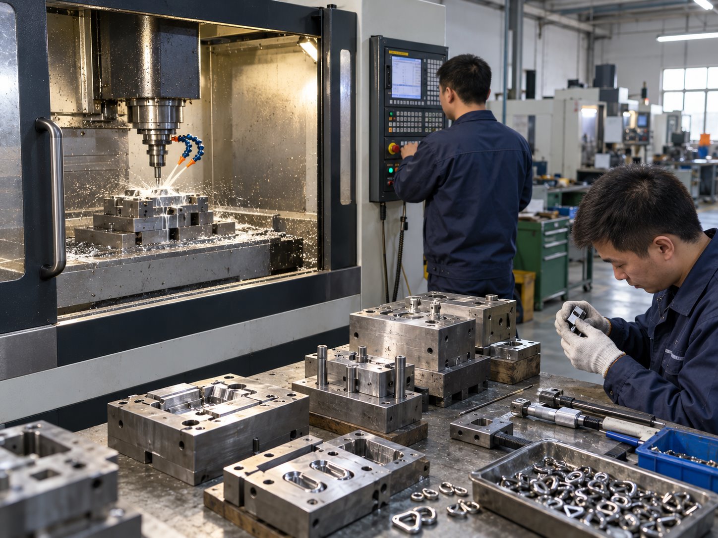
We combat thermal shrinkage through aggressive conformal cooling engineering. Our CNC centers drill high-pressure cooling circuits inside the H13 die blocks, circulating treated water at 65°C to 80°C. By precisely chilling the heavy sections while maintaining warmth in the thin runners, we achieve directional solidification from the furthest extremities back toward the pressurized gate, feeding shrinkage voids completely before the sprue seals.
5. Cold Shuts and Lamination Flaws: Why Thin Profiles Crack Under Strain
A cold shut (or cold lap) occurs when two streams of molten zinc flow around a core pin or hole, meet on the opposite side, and fail to fuse together completely into a continuous metallic bond. Under optical magnification, a cold shut looks like a deep, clean seam or hairline crack running straight through the keychain.
The root cause is premature freezing. If the molten metal temperature drops below 380°C before the filling phase completes, or if the mold surface temperature is too cold (below 140°C), the advancing fluid fronts form a solid oxide skin. When the two oxide-covered fronts collide, the hydraulic pressure is insufficient to break through the oxide film. While the part may appear intact cosmetically, the seam possesses virtually zero tensile strength and will snap cleanly in two under a modest 5 kgf bending load.
We eliminate cold shuts through real-time thermal monitoring. Our die-casting machines are equipped with infrared pyrometer sensors that monitor die face temperatures before every shot. If the die temperature drops below 160°C, the automated PLC delays injection and triggers internal electric heating cartridges. Furthermore, we maintain molten furnace pot temperatures at a strictly calibrated 420°C ± 5°C, ensuring sufficient superheat to maintain low viscosity throughout the entire injection stroke.
6. Surface Finishing and Polishing: The Dangerous Skin Layer Removal
A die-cast zinc part possesses a unique dual microstructure. Upon contact with the chilled steel die, the outer surface solidifies in milliseconds, forming a dense, non-porous 'chill skin' approximately 0.15mm to 0.25mm thick with ultra-fine grain size. Beneath this dense outer skin lies a coarser, dendritic crystalline core that inevitably contains micro-porosities.
The mortal sin committed by inexperienced polishing workers is over-grinding. If a heavy-handed polisher grinds away more than 0.20mm of metal to remove a parting line burr, they breach the dense chill skin, exposing the porous underlying dendritic core directly to the atmosphere.
When the part is subsequently submerged in chemical electroplating baths, cleaning acids and cyanide-free copper plating solutions penetrate deep into these porous capillary fissures. Rinsing water cannot flush out these trapped chemical salts. Weeks later, the trapped acidic salts react with the surrounding zinc, releasing pressurized hydrogen gas that pushes outward against the nickel-gold electroplate, creating the dreaded electroplating blister.
At Naike, our centrifugal tumbling SOP is calibrated with digital laser micrometer tracking to remove strictly 0.03mm to 0.05mm of surface material during deburring. We preserve 80% of the dense chill skin intact, providing an impenetrable, glass-smooth barrier for subsequent electroplating.
7. Engineering Best Practices for B2B Hardware Designers
If you are designing custom metal keychains for corporate promotions or retail lifestyle lines, adopting the following design for manufacturing (DFM) principles will eliminate 95% of casting defects before tooling begins:
1. Maintain Uniform Wall Thickness: Strive for a uniform cross-section between 2.0mm and 3.2mm. Avoid sudden transitions from 6.0mm blocks to 1.2mm ribs.
2. Provide Generous Draft Angles: Incorporate at least 1.5° to 2.0° of draft on all internal and external sidewalls to prevent ejection galling.
3. Radiused Internal Corners: Sharp 90-degree internal corners concentrate stress and cause turbulence. Specify a minimum fillet radius of R0.5mm on all internal cavity edges.
4. Core Out Thick Bosses: If your design features an ultra-thick 3D emblem, core out the backside with recessed pockets to eliminate mass, save weight, and prevent shrinkage sink marks.